How to Overcome Quadruped Robot Speed Limits?
What limits the speed of quadruped robots is rarely one isolated component. The real constraint appears when motors, batteries, joints, sensors, and foot contacts interact at high speed. A robot may have powerful actuators, yet still stumble when its feet touch uneven ground. Its controller must predict the next foothold within milliseconds. Small timing errors can become large body movements.
Dr. Marco Hutter, a leading researcher in legged robotics, has stated, “Legged robots have to deal with highly dynamic and uncertain interactions with the environment.” This observation explains why speed improvements require more than simply increasing motor power. Engineers must reduce actuator weight, improve torque-to-mass ratios, and manage heat inside compact joints. Battery discharge also matters. A fast sprint can drain energy quickly and lower voltage during operation.
The solution begins with careful system balance. Lightweight carbon structures can reduce inertia around the legs. Model-based control can coordinate hip, knee, and ankle movements more precisely. High-frequency force sensing can help the robot recognize slipping before a fall develops. Better foot design may also improve traction on gravel, wet concrete, or loose soil.
Still, some assumptions deserve criticism. Faster is not always better. A robot that reaches top speed only on a smooth laboratory floor has limited practical value. Real progress should combine speed, stability, endurance, and safe recovery. That balance remains difficult. Sometimes, the fastest design is not the most useful one.
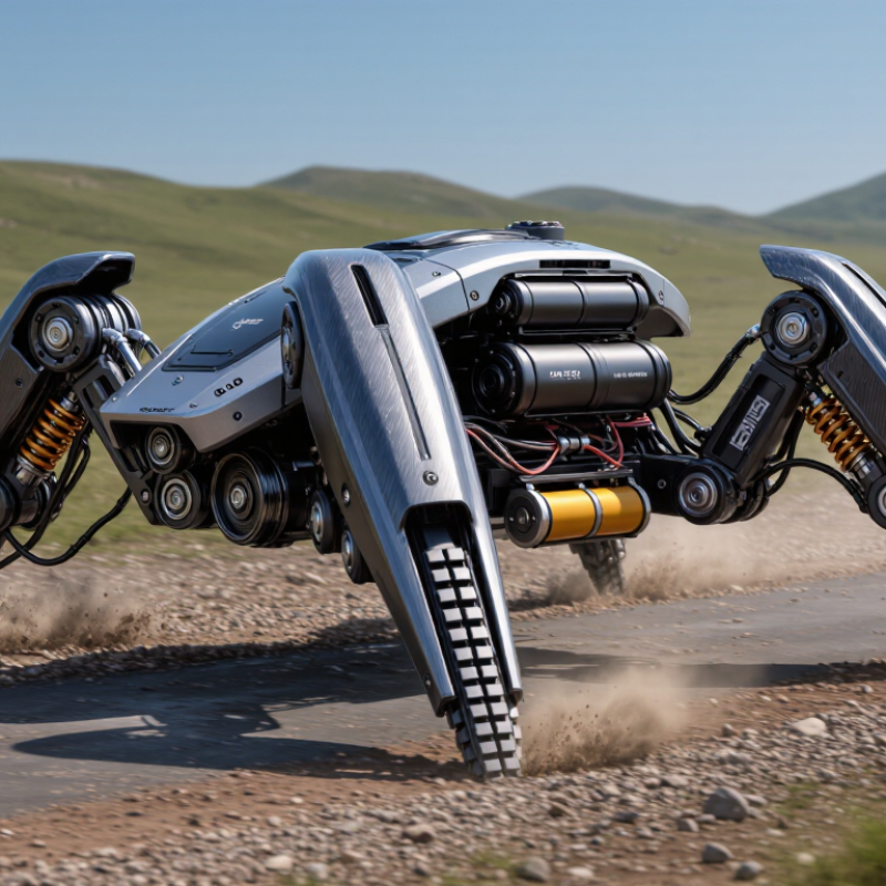
Quadruped robot speed limits become clearer when comparing 1.6 m/s with 6 m/s. The faster figure is 3.75 times higher. However, published peak speed is not the same as dependable working speed. It usually applies to smooth ground, a charged battery, and a controlled route. Outdoor sites add loose gravel, wet soil, steps, cables, and sudden turns. Each condition can reduce stability and usable speed.
Field testing should measure more than maximum velocity. Record speed, stopping distance, battery temperature, falls, and recovery time across repeated routes. ISO 8373:2021 standardizes robotics vocabulary, but it does not define a universal quadruped speed test. This gap makes product comparisons imperfect. A 6 m/s platform may cross an open path quickly, while a 1.6 m/s platform could deliver better inspection quality near people or equipment.
Industry scale also demands caution. The International Federation of Robotics reported 541,302 industrial robot installations worldwide in 2023. That figure shows strong automation growth, but it does not validate outdoor legged-robot speed claims. Buyers should request test conditions, not impressive numbers alone. I would question any specification without terrain, payload, incline, and braking data. The uncomfortable detail is simple: faster motion can shorten mission time, yet it can also increase energy use, sensor noise, and recovery risk. A practical limit may be lower.
Quadruped robot speed often depends more on gait timing than motor power. Raising step frequency can improve forward velocity, but it also shortens the time available for foot placement and body correction. At higher rates, small timing errors become visible as hip vibration, toe dragging, or sudden yaw. Stable motion depends on coordinating duty factor, stride length, and contact sequence. Measure every step.
A practical approach begins with a moderate trot and gradual frequency increases. Keep the duty factor high enough to preserve support during acceleration. Use joint-position feedback with inertial measurements to detect body roll and pitch. When the torso tilts, adjust swing-leg timing rather than forcing larger joint movements. This response is usually smoother and consumes less energy. Foot trajectories should also lift slightly higher on uneven ground, but excessive clearance wastes time and power.
Testing should use repeatable surfaces, fixed payloads, and logged sensor data. Compare speed, slip rate, body acceleration, and motor temperature after each frequency change. A short outdoor trial can reveal problems hidden on a flat laboratory floor. In practice, the fastest setting is rarely the most reliable one. I have found that a small reduction in frequency often improves average speed over a full route. The trade-off is easy to underestimate. Further tuning may still be needed when terrain, battery voltage, or payload changes.
| Control Dimension | Reference Condition | Typical Engineering Range | Effect on Speed | Recommended Optimization Action |
|---|---|---|---|---|
| Gait Type | Low-speed walking to high-speed running | Walk: 0.5–1.5 Hz Trot: 1.5–3.0 Hz Bound: 2.0–4.0 Hz |
Higher-frequency gaits can increase speed, but they reduce the time available for corrective control. | Use a smooth gait transition based on measured velocity, body pitch, and contact confidence rather than fixed speed thresholds. |
| Step Frequency | Stable trot on level ground | Approximately 1.5–3.0 steps per second per leg cycle | Increasing frequency raises forward speed when step length is maintained. | Increase frequency gradually, for example in 0.1–0.2 Hz increments, and limit acceleration of the frequency command. |
| Duty Factor | Fraction of each gait cycle that a foot remains in contact with the ground | Walk: above 0.50 Trot: about 0.50 Running gaits: below 0.50 |
Lower duty factors permit faster motion but reduce the number of supporting legs during each cycle. | Reduce duty factor only after contact timing, foot placement, and body-state estimation are reliable. |
| Step Length | Forward displacement produced by one gait cycle | Speed is approximately equal to step frequency × step length | Increasing step length without changing frequency can also raise speed, but excessive reach increases slip and joint loading. | Increase step length within the measured workspace and keep the foot touchdown point inside the support region. |
| Phase Coordination | Relative timing among the four legs | Trot commonly uses a phase difference of approximately 0.50 cycle between diagonal pairs | Phase errors can create uneven loading, lateral sway, and loss of traction at higher frequencies. | Use phase feedback from contact sensors or estimated ground reaction forces to correct timing online. |
| Support Polygon | Area enclosed by the feet currently in contact with the ground | Static walking generally maintains at least three supporting legs during normal steps | A smaller or rapidly changing support polygon lowers static stability during acceleration. | Coordinate the center of mass projection with the support polygon before increasing swing-leg speed. |
| Dynamic Stability Margin | Distance between the predicted motion state and the boundary of stable operation | Maintain a positive margin throughout stance and touchdown events | A declining margin indicates that frequency is being increased faster than the controller can stabilize the body. | Treat stability margin as a constraint in model-predictive or whole-body control instead of optimizing speed alone. |
| Body Pitch and Roll | Trunk orientation during acceleration and foot exchange | Keep orientation errors within the robot’s tested control envelope; use smaller limits on low-friction surfaces | Large angular oscillations consume actuator bandwidth and reduce touchdown accuracy. | Add velocity-dependent trunk stabilization and compensate for predictable pitch caused by acceleration. |
| Ground Contact Time | Duration from touchdown to liftoff | Shorter contact time generally accompanies higher step frequency | Excessively short contact time can prevent force buildup and cause foot slip or bouncing. | Tune touchdown compliance and vertical impulse before shortening stance duration. |
| Foot Clearance | Vertical distance between the swing foot and the terrain | Use terrain-dependent clearance; higher clearance is needed for obstacles but increases swing effort | Insufficient clearance causes toe strikes, while excessive clearance limits frequency and consumes energy. | Adapt clearance to terrain height estimates and reduce swing duration with jerk-limited trajectories. |
| Slip Ratio | Difference between commanded and actual foot-ground motion | Target a low, repeatable slip ratio; the acceptable value depends on terrain friction and load | Slip increases when tangential force exceeds available friction, limiting practical speed. | Estimate contact conditions and reduce tangential force or step acceleration when slip is detected. |
| Actuator Bandwidth | Ability of the joint controller to track fast position, velocity, and torque changes | Control bandwidth must exceed the dominant gait frequency with sufficient phase margin | Insufficient bandwidth produces tracking lag, delayed touchdown, and unstable leg forces. | Profile commands, reduce high-frequency trajectory noise, and verify tracking error under loaded conditions. |
| Thermal and Power Limit | Continuous operation at elevated frequency | Peak torque and current are limited by motor, drive, battery, and cooling capability | Higher frequency increases mechanical work and may trigger current, temperature, or voltage protection. | Monitor joint temperature, current, and battery voltage; use frequency derating when limits are approached. |
A quadruped robot rarely reaches higher speed through software alone. The limiting factor is often power density: usable watts per kilogram at each joint. To move beyond a 1.5 m/s operating speed, engineers must deliver stronger bursts without making the legs heavier. That balance starts with compact motors, efficient gearing, and short power paths. Every gram matters. A heavier actuator increases swing effort and ground impact. Measurements should include torque, current, temperature, and recovery time, not speed alone.
A practical development test uses a marked track, force sensors, and thermal probes. Run repeated sprints, then inspect motor temperature and battery voltage sag. If speed drops after three runs, the system lacks sustainable power density. Better cooling can help, but it may add fans, ducts, and vulnerable openings. Higher voltage can reduce cable losses, while precise current control protects the drivetrain during sudden foothold changes. Mechanical compliance also matters. Elastic elements can store energy during landing and return it during push-off. The result is not free. Control becomes harder.
Field reliability should guide every upgrade. A robot that reaches 2 m/s once may fail on gravel, ramps, or wet flooring. Validate acceleration, braking, turning, and repeated starts across realistic surfaces. Laboratory gains often shrink outdoors. That is the uncomfortable part. Designers should log joint temperature, slip events, energy per meter, and maintenance intervals. A small speed increase with stable thermal margins may outperform a dramatic peak figure. Power density is not merely a motor specification. It is a system decision involving structure, battery, control, cooling, and operator safety.
How to Overcome Quadruped Robot Speed Limits?
Reduce Thermal and Battery Constraints for Sustained High-Speed Runs
A quadruped robot may reach high speed briefly, then slow when heat builds. Thermal limits often control performance more than motor power. During field testing, motor housings can become uncomfortable after several minutes of repeated sprints. Internal winding temperatures rise even faster. Small temperature sensors near each actuator provide better warnings than surface checks alone.
Improve cooling without adding excessive weight. Open airflow paths around motor housings and use conductive frames to spread heat. Reduce unnecessary friction in joints, since wasted energy becomes heat. A useful control strategy alternates leg loading and adjusts stride length during sharp turns. It protects actuators while preserving forward speed. Do not ignore recovery periods. Short pauses can prevent long thermal shutdowns.
Battery voltage sag creates another hidden limit. High current draw lowers voltage, especially when the battery charge falls below its preferred operating range. Monitor current, voltage, and temperature together. Set conservative low-voltage thresholds before testing maximum speed. A smaller battery may reduce weight, but it can heat faster and lose voltage sooner. This trade-off is easy to underestimate. In my view, energy management still needs refinement. A robot that runs fast for thirty seconds may perform worse than one maintaining speed for ten minutes. Real progress comes from measuring complete runs, not celebrating one impressive sprint.
Speed alone proves very little. A useful benchmark records speed, payload, terrain, and safety together. The 2024 World Robotics report recorded 541,302 industrial robot installations worldwide in 2023. That scale raises expectations for mobile robots, but quadruped testing needs different evidence. Record walking speed across concrete, gravel, wet grass, ramps, and loose soil. Measure it with a loaded platform, not an empty chassis.
Payload changes everything. Test at zero, half, and rated payloads. Record average speed, battery use, motor temperature, foot slips, and recovery time. ISO 9283 provides a practical framework for robot performance testing, including repeatability and path accuracy. Its principles can strengthen quadruped trials, even though the standard was not written specifically for legs. A 10-minute sprint is not enough. Run repeated routes until performance becomes boring.
Safety must be measurable. Use stopping distance, fall frequency, obstacle-clearance success, and human-detection response time. NIST’s mobile robot evaluation work shows why repeatable environments and defined metrics matter. In field tests, I would also log near-falls, because successful recovery can hide poor stability. This is where our method remains imperfect. Weather, soil moisture, and operator decisions still distort results. Publish raw data, test conditions, and failed runs. Independent observers should reproduce the route. Faster is useful only when the robot remains controlled, useful, and safe.
Higher step frequency can increase forward speed without adding motor power. It also leaves less time for foot placement and body correction. Small timing errors may cause hip vibration, toe dragging, or sudden yaw. Faster is not always better.
Begin with a moderate trot and raise frequency gradually. Keep the duty factor high enough to maintain support during acceleration. Record speed, slip rate, body acceleration, and motor temperature after each change. Small steps matter.
Joint-position feedback and inertial measurements can detect body roll and pitch. When the torso tilts, adjust swing-leg timing instead of forcing larger joint movements. This usually produces smoother motion with lower energy use. More testing may be needed.
Raise the feet slightly higher when the surface becomes uneven. Too much clearance wastes time and power. Watch for toe contact with stones, edges, or shallow floor gaps. The ideal height is easy to underestimate.
Use repeatable surfaces, fixed payloads, and logged sensor data. Test on a marked track when possible. Include a short outdoor trial, because flat floors hide many problems. Conditions still vary.
Power density often becomes the main limit. The system needs strong joint bursts without adding heavy legs. Compact motors, efficient gearing, and short power paths can help. Every gram matters.
Run repeated sprints with force sensors and thermal probes. Measure torque, current, battery voltage sag, temperature, and recovery time. If speed falls after three runs, usable power may be insufficient. Peak speed alone misleads.
Better cooling can protect motors, but fans, ducts, and openings add weight or vulnerability. Higher voltage can reduce cable losses. Precise current control helps protect the drivetrain during sudden foothold changes. Control becomes harder.
A robot may reach 2 meters per second once, then fail on gravel, ramps, or wet flooring. Validate acceleration, braking, turning, and repeated starts across realistic surfaces. Log slip events, energy per meter, temperatures, and maintenance intervals. Outdoor gains often shrink.
Understanding what limits the speed of quadruped robots requires examining more than motor output alone. Practical speed is shaped by gait stability, step frequency, actuator power density, body balance, terrain interaction, and the ability to manage heat and battery consumption. A robot may reach a high peak speed in ideal conditions, yet operate much more slowly when carrying payloads, crossing uneven ground, or running for extended periods. Raising step frequency can improve forward motion, but only when control algorithms maintain reliable foot placement, posture, and recovery from disturbances.
To overcome these limits, designers should combine faster and more efficient actuators with lightweight structures, responsive gait control, improved thermal pathways, and higher-capacity power systems. Progress should be measured through repeatable benchmarks that evaluate maximum speed, sustained speed, payload, terrain difficulty, energy use, and safety. This comprehensive approach helps answer the question, “What limits the speed of quadruped robots,” while turning short demonstrations into dependable high-speed performance.

Excitech Robot